

Table of Contents
1. Safety instructions ................................................................................................................... 1
2. General description .................................................................................................................. 2
2.1. Inverter ........................................................................................................................ 2
2.2. Solar charge controller ...................................................................................................... 2
2.3. ON/OFF/CHARGER-ONLY switch ........................................................................................ 2
2.4. LED diagnosis and monitoring ............................................................................................. 2
2.5. The VictronConnect app .................................................................................................... 3
2.6. Bluetooth ..................................................................................................................... 3
2.7. VE.Direct port ................................................................................................................ 3
2.8. Remote on/off control ....................................................................................................... 3
2.9. Temperature sensor ......................................................................................................... 4
2.10. BMS communication ....................................................................................................... 4
3. Installation ............................................................................................................................. 5
3.1. Physical installation ......................................................................................................... 5
3.1.1. Location ............................................................................................................ 5
3.1.2. Mounting ........................................................................................................... 5
3.2. Electrical installation ........................................................................................................ 6
3.2.1. Connection to the battery ......................................................................................... 6
3.2.2. Solar connection .................................................................................................. 6
3.2.3. AC output connection ............................................................................................. 6
3.2.4. Chassis to ground connection ................................................................................... 7
3.2.5. Remote connector ................................................................................................. 7
3.2.6. VE.Direct connection ............................................................................................. 9
3.2.7. SUN Inverter system example ................................................................................... 9
4. Configuration ....................................................................................................................... 10
4.1. AC output voltage and frequency ........................................................................................ 10
4.2. ECO mode and ECO settings ............................................................................................ 10
4.3. Low battery alarm and charge detect settings ......................................................................... 10
4.3.1. Dynamic cut off .................................................................................................. 11
4.4. Battery settings ............................................................................................................ 12
4.4.1. Battery charge algorithm settings ............................................................................. 13
4.5. VE.Smart Networking ..................................................................................................... 16
4.5.1. VE.Smart Networking setup .................................................................................... 17
4.6. Firmware update ........................................................................................................... 19
4.7. Reset settings to default .................................................................................................. 19
5. Operation ............................................................................................................................ 20
5.1. Inverter ...................................................................................................................... 20
5.1.1. ECO Mode ....................................................................................................... 20
5.2. Solar charger ............................................................................................................... 20
5.2.1. CHARGE mode .................................................................................................. 20
5.3. Power and Alarm LED definitions and troubleshooting ............................................................... 20
5.4. STATE LED definitions .................................................................................................... 23
5.5. Protections and automatic restarts ...................................................................................... 23
5.6. Monitoring via VictronConnect ........................................................................................... 24
5.7. Monitoring via a GX device, GlobalLink and the VRM portal ......................................................... 25
6. Technical specifications .......................................................................................................... 26
6.1. Technical specifications SUN Inverter ................................................................................... 26
7. Appendix ............................................................................................................................. 28
7.1. AC outlet .................................................................................................................... 28
7.2. Connection overview ...................................................................................................... 28
7.3. Installation information neutral to ground connection ................................................................. 28
7.4. Dimensions ................................................................................................................. 29
SUN Inverter Manual

1. Safety instructions
General
Please read the documentation supplied with this product first, so that you are familiar with the safety signs and directions before
using the product. This product is designed and tested in accordance with international standards. The equipment should be used
for the designated application only.
• WARNING - These servicing instructions are for use by qualified personnel only. To reduce the
risk of electric shock, do not perform any servicing other than that specified in the operating
instructions unless you are qualified to do so.
• WARNING - ELECTRIC SHOCK HAZARD - The product is used in conjunction with a permanent
energy source (battery). Input and/or output terminals may still be dangerously energized, even when the
equipment is switched off. Always disconnect the battery before carrying out maintenance or servicing the
product.
• The product has no internal user-serviceable components. Do not remove the front plate or operate the
product if any panels have been removed. All servicing must be undertaken by qualified personnel.
• Please read the installation instructions in the installation manual before installing the equipment.
• This is a Safety Class I product (supplied with a protective grounding terminal). The chassis must be
grounded. A grounding point is located on the outside of the product. Whenever it is likely that the
grounding protection has been damaged, the product must be turned off and secured against unintended
operation; please contact qualified service staff.
• The AC output is isolated from the DC input and the chassis. Local regulations may require a true neutral.
In this case, one of the AC output wires must be connected to the chassis,
and the chassis must be
connected to a reliable ground. Please note that a true neutral is needed to ensure the correct operation
of an earth leakage circuit breaker.
• Ensure that the equipment is used under the correct ambient conditions.
Never operate the product in a wet or dusty environment.
Never use the product where there is a risk of gas or dust explosions.
• Ensure that there is adequate free space (10 cm) for ventilation around the product and check that the
ventilation vents are not blocked.
• This appliance is not intended for use by persons (including children) with reduced physical, sensory or
mental capabilities, or lack of experience and knowledge unless they have been given supervision or
instruction concerning the use of the appliance by a person responsible for their safety.
• Children should be supervised to ensure that they do not play with the appliance.
• Use of an attachment not recommended or sold by the marine unit manufacturer may result in a risk of fire,
electric shock, or injury to persons.
Transport and storage
Ensure that the mains power and battery leads have been disconnected before storing or transporting the product.
No liability can be accepted for any transport damage if the equipment is shipped in non-original packaging.
Store the product in a dry environment; the storage temperature must be between -20°C and 60°C.
Consult the battery manufacturer's manual in respect of transport, storage, charging, recharging and disposal of the battery.
SUN Inverter Manual
Page 1 Safety instructions

2. General description
2.1. Inverter
Proven reliability
The inverter uses a full bridge with toroidal transformer topology that has proven its reliability over many years. It is short circuit
proof and protected against overheating, whether due to overload or high ambient temperature.
High startup power
To start loads such as: power converters for LED lamps, filament lamps or electric tools.
AC output socket
The inverter has an IEC-320 output socket and ships together with an IEC-320 male plug.
ECO mode
ECO mode reduces the inverter power consumption by approximately 85% by going into standby operation when there are no
loads connected to the inverter. When the inverter has been switched to ECO mode, it will enter standby operation when the load
is less than a preset value. While in standby operation, the inverter will check every few seconds if the load has increased again.
If the load has increased, the inverter will leave standby operation and resumes regular inverter operation. The sensitivity of the
ECO mode is configurable.
Fully configurable
• AC output voltage and frequency.
• Low battery voltage cut-off and restart levels.
• ECO mode on/off and ECO mode sensitivity level.
To transfer the load to another AC source: The automatic transfer switch
For inverters we recommend our Filax2 automatic transfer switch. The Filax2 features a very short switchover time (less than 20
milliseconds) so that computers and other electronic equipment will continue to operate without disruption. Alternatively use an
inverter/charger with built-in transfer switch.
2.2. Solar charge controller
The SUN inverter is equipped with a PWM solar regulator. Solar panels can be directly connected to the SUN inverter. Solar
power will be used to charge the batteries or help to provide energy to the inverter AC load.
The solar charger is fully configurable, for more information see the CHARGE mode [20] chapter.
2.3. ON/OFF/CHARGER-ONLY switch
The inverter is equipped with a 3-way switch that performs the following functions:
• ON - Switches the inverter and the solar charger on.
• OFF - Switches the inverter and the solar charger off.
• CHARGER-ONLY - Switches only the solar charger on, while the inverter is switched off.
2.4. LED diagnosis and monitoring
The inverter indicates basic operational information and alarms via its LEDs:
• Inverter state.
• Charge stage.
• Overload warning or alarm.
• Over temperature warning or alarm.
• Low battery voltage warning or alarm.
• High DC ripple warning or alarm.
SUN Inverter Manual
Page 2 General description
Additional parameters can be monitored via VictronConnect:
• Inverter state.
• Battery voltage.
• AC output voltage.
• Percentage of nominal AC load.
• Solar power and voltage.
• Warning and alarms.
For the full list of all LED indications and monitoring parameters see the Operation [20] chapter.
2.5. The VictronConnect app
The VictronConnect app is used to monitor, control and configure the inverter. The app can be installed on a phone, tablet or
computer. The app is available for Android, iOS, Windows and macOS. The app either communicates via Bluetooth or via USB
interfaced to the VE.Direct port.
For more information about the app and to download the app see the VictronConnect product page.
2.6. Bluetooth
The inverter has built-in Bluetooth.
Bluetooth (but also a VE.Direct connection) can be used to communicate with the VictronConnect app.
Bluetooth can also be used to communicate with the VE.Smart Networking and with the Smart Battery Sense to share battery
voltage and temperature data to all devices connected to the VE.Smart Networking.
2.7. VE.Direct port
The inverter is equipped with a VE.Direct port. This port can be used to connect the inverter to:
• The VictronConnect app via a VE.Direct to USB interface.
• The VictronConnect app via a VE.Direct Bluetooth Smart dongle.
• A GX monitoring device, such as the Cerbo GX. Note that an additional VE.Direct cable is needed for this.
• The GlobalLink 520. Note that an additional VE.Direct cable is needed for this.
2.8. Remote on/off control
The inverter can be remotely turned on or off in the following ways:
• Via the VictronConnect app.
• With an (optional) external switch connected to the remote connector.
• With the (optional) Phoenix Inverter Control VE.Direct panel connected to the remote connector.
• From a BMS (Battery Management System) connected to the remote connector.
• Via a GX device and/or the VRM portal (optional).
For more information see the Remote connector [7] chapter.
SUN Inverter Manual
Page 3 General description

2.9. Temperature sensor
For temperature compensated charging or low temperature detection, a wired temperature sensor, the Temperature sensor
Quattro, MultiPlus and GX Device or a wireless temperature sensor, the Smart Battery Sense can be used. These are optional
extras and are not included with the inverter.
For more information see the Battery temperature sensor [8] chapter.
2.10. BMS communication
The remote connector can be used by a lithium Battery Management System (BMS) to control the SUN Inverter, to stop the
inverter when the batteries are too far discharged or to stop the solar charger when the batteries are overcharged or when the
battery temperature is below 5°C.
SUN Inverter Manual
Page 4 General description

3. Installation
• This product should be installed by a qualified electrician.
• During installation ensure that the remote connector with wire bridge is removed (or switch off the remote
on/off switch if installed) to be sure that the inverter cannot be switched on unexpectedly.
3.1. Physical installation
For a dimension drawing of the inverter, see the Appendix [28] of this manual.
3.1.1. Location
To ensure a trouble free operation of the inverter, it must be used in locations that meet the following requirements:
• Avoid any contact with water. Do not expose the inverter to rain or moisture.
• Install the inverter in a dry and well-ventilated area.
• For best operating results, the inverter should be mounted on a flat surface.
• Mount as close as possible to the batteries. Try and keep the distance between the product and the battery to a minimum in
order to minimize cable voltage losses.
• There should be a clear space of at least 10cm around the appliance for cooling. Do not obstruct the airflow around the inverter.
When the inverter is running too hot, it will shut down. When the inverter has reached a safe temperature level, the unit will
automatically restart again.
• Do not place the unit in direct sunlight. The ambient air temperature should be between -20°C and 40°C (humidity <95%
non-condensing). Note that in extreme situations the inverter’s case temperature can exceed 70°C.
• Excessive high ambient temperature will result in a reduced service life, reduced charge current, reduced
peak power rating or shutdown of the inverter.
• Never mount the inverter directly above the batteries.
• For safety purposes, this product should be installed in a heat resistant environment if it is used with
equipment where a substantial amount of power is to be converted. You should prevent the presence of e.g.
chemicals, synthetic components, curtains or other textiles, etc., in the immediate vicinity.
3.1.2. Mounting
Mount the inverter against a sturdy wall or horizontally on a suitable ground surface.
Mount the inverter with four screws vertically up- or downwards or horizontally up- or downwards. See below table and figure for
the best mounting options.
Mounting directions.
# Mounting type Recommended? IP rating Notes
1 Ceiling mounting (inverted). No n/a
2 Base mounting Yes IP21
SUN Inverter Manual
Page 5 Installation
# Mounting type Recommended? IP rating Notes
3 Vertical wall mounting, fan at the
bottom.
Yes IP20 Be aware that potentially small
objects or dust can fall into
the inverter through the ventilation
openings at the top.
4 Vertical mounting, fan on top. No n/a
5 Horizontal wall mounting. Yes IP20
3.2. Electrical installation
For a connection overview drawing of the inverter, see appendix Connection overview [28].
3.2.1. Connection to the battery
In order to fully utilize the full capacity of the inverter, it is important to use batteries with sufficient capacity and battery cables with
sufficient cross section.
The inverter is fitted with an internal DC fuse. If the battery cable length is more than 1.5m, an additional fuse or DC circuit
breaker must be added to the battery cable, located close to the battery.
See below table for the recommended battery cable cross section, internal fuse information and the minimum recommended
battery capacity for each inverter model.
Inverter
model
Cable cross section
0-1.5m
Cable cross section
1.5-m
Internal fuse
(Littlefuse)
Fuse replaceable? Minimum
battery
capacity
12/250 4mm² 6mm² 2 x 30A, 32V, ATOF No 30Ah
24/250 2.5mm² 4mm² 30A, 32V ATOF No 20Ah
Sufficient cable thickness and appropriate sized batteries are an important factor. Please consult your supplier or see the relevant
sections of our books: Energy Unlimited and Wiring Unlimited, both downloadable from our website.
Battery connection procedure
• Use insulated tools in order to avoid shorting the battery terminals.
• Avoid shorting the battery cables.
Proceed as follows to connect the battery cables:
• Be aware that reverse polarity connection of the battery cables (+ to – and – to +) will cause damage to the inverter.
• Connect the battery cables to the + (red) and the - (black) battery terminals.
• Secure the battery connections tightly. A tight connection will reduce the contact resistance as much as possible.
3.2.2. Solar connection
• Be aware that reverse polarity connection of the solar panel wires can cause damage to the inverter.
• Connect the solar panel cables to the positive (red) and the negative (black) PV terminals.
• Secure the PV connections tightly. A tight connection will reduce the contact resistance as much as possible.
Do not connect a battery or DC Power supply to the Solar connection. This will cause damage to the inverter.
3.2.3. AC output connection
The inverter is equipped with the following AC outlet:
• IEC-320 (male plug included).
For a photo of the AC outlet type, see appendix AC outlet [28].
The inverter does not have a fuse in the AC output. The AC cabling is protected by a fast-acting current limiter in case of a short
circuit and an overload detection mechanism which mimics the characteristics of a fuse (i.e. faster shutdown with larger overload).
It is important to size your wiring properly, based on the inverter’s power rating.
SUN Inverter Manual
Page 6 Installation
Never connect the AC output of the inverter to another AC source, such as a household AC wall outlet or a generator.
• The inverter has a floating ground. To ensure proper functioning of a GFCI (or RCCB, RCB or RCD) to be
installed in the AC output circuit of the Inverter, an internal or external neutral to ground connection needs to
be made. For more information see appendix Installation information neutral to ground connection [28].
3.2.4. Chassis to ground connection
Wire size for connecting the inverter chassis to ground:
The earth conductor from the earth lug on the chassis to ground should have at least half the cross-section of the conductors
used for the battery connection.
The maximum conductor size that fits the earth lug is 25 mm². Use the table below to find the correct cross-section for the earth
conductor.
Battery cable Ground cable
1.5 mm² ≥ 0.75 mm²
2.5 mm² ≥ 1.5 mm²
4 mm² ≥ 2.5 mm²
6 mm² ≥ 4 mm²
3.2.5. Remote connector
Remote on/off control of the inverter can be achieved with a simple on/off switch connected to the inverter remote connector.
The inverter will switch on when it has been switched to ON via the ON/OFF/CHARGER-ONLY swicht
and when:
• Contact is made between the remote connector H (left) terminal and L (right) terminal, for example via the wire bridge, a switch
or the Inverter control panel.
• Contact is made between the remote connector H (left) terminal and battery positive.
• Contact is made between the remote connector L (right) terminal and battery negative.
Some usage examples of the remote connector are:
• If the inverter is situated in a vehicle and is only allowed to operate when the engine is running. Connect the remote connector
H (right) terminal to the vehicle ignition switch.
• If the inverter is connected to a lithium battery the inverter can be controlled by the lithium battery BMS.
• For safety purposes, the inverter can be turned off completely by removing the remote connector. Do this by
pulling the remote connector out of its socket. This ensures that the inverter cannot be turned on anymore
via its switch or Bluetooth. The user can now be certain that the inverter is definitely turned off and it cannot
be accidentally turned back on by another user.
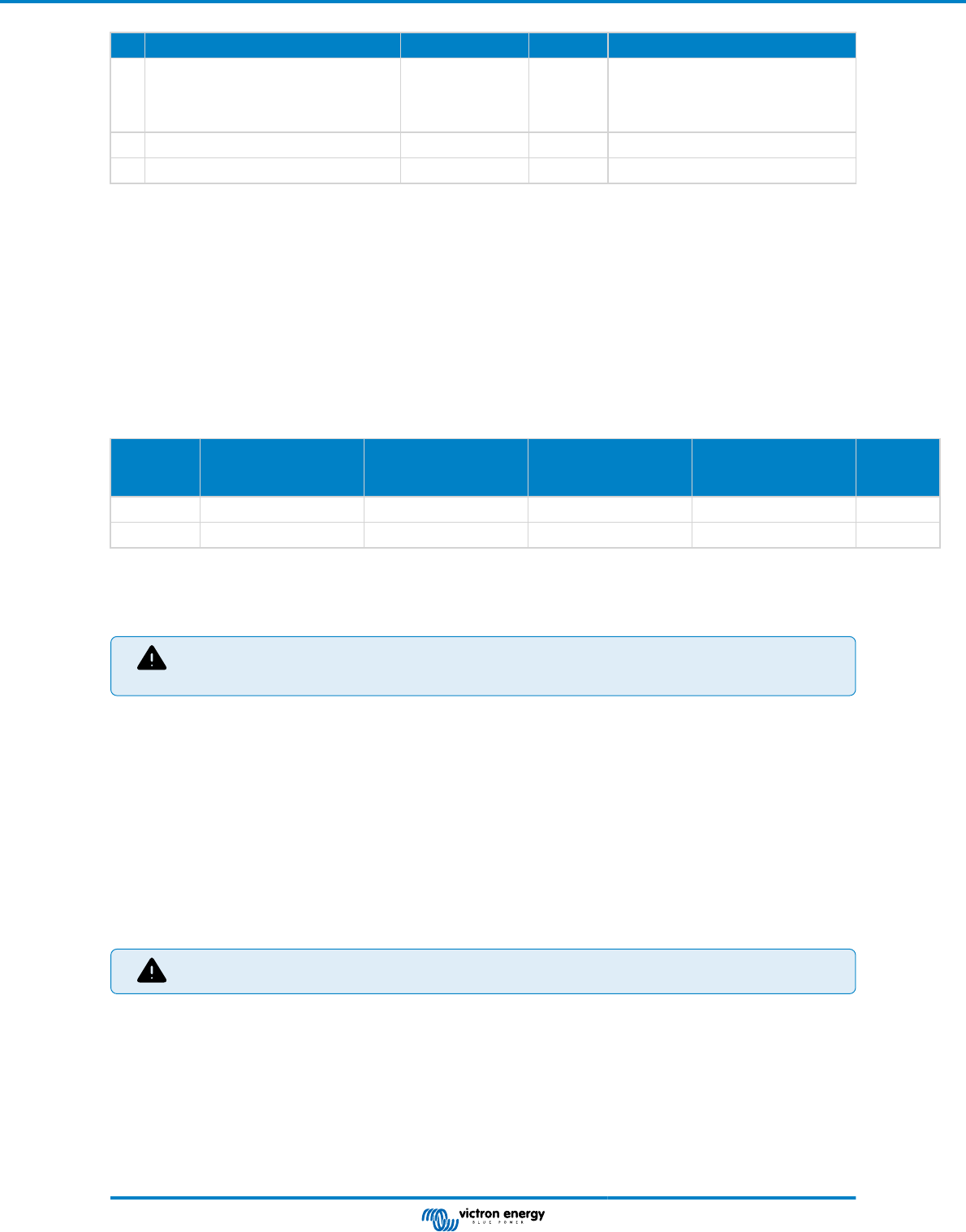
Inverter control panel
If a Phoenix Inverter Control VE.Direct panel is used, it needs to be connected to the inverter remote connector as is indicated in
below image. Note that the connection is polarity dependent for proper operation.
Connecting to a BMS
The remote connector can be used to control the inverter and its solar charger from a lithium battery BMS (Battery Management
system) in the following way:
• If both the H (left) and L (right) terminal are floating or pulled to ground (0V) the inverter and solar charger are off.
SUN Inverter Manual
Page 7 Installation
• If the H (left) terminal is pulled high (battery voltage), the battery is allowed to be discharged and the inverter is on.
• If the L (right) terminal is pulled high (battery voltage), the battery is allowed to be charged and the solar charger is on.
• If both the H (left) terminal and L (right) terminal are pulled high (battery voltage), the battery is allowed to be charged and
discharged and both the solar charger and inverter are on.
• If the H (left) and L (right) terminal are interconnected (wire loop) normal condition, the inverter and solar charger are on.
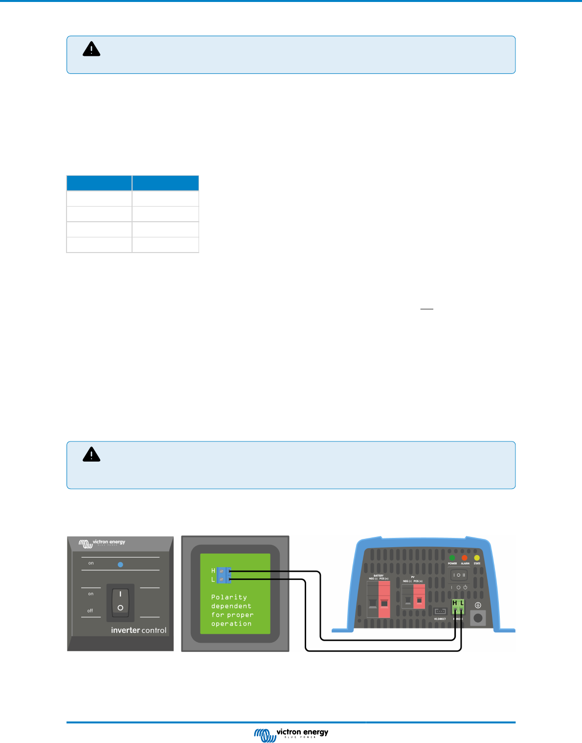
• Note that the BMS function overrules the ON/OFF/CHARGE switch as well as switching the unit via the
VictronConnect app.
REMOTE connector - location H and L terminal.
Battery temperature sensor
Battery temperature information can be used by the SUN inverter to do the following:
• In case of lead-acid batteries, to facilitate temperature compensated charging. The charge voltage is reduced when the
batteries are hot and the charge voltage is increased when the batteries are cold.
• In case of lithium batteries, to stop battery charging at very low temperatures (generally below 5°C).
Battery temperature can be obtained in two ways:
• From a VE.Smart Networking, for more information on this see the VE.Smart Networking [16] chapter.
• From an external temperature sensor, the Temperature sensor QUA PMP GX Device.
• Note that the above temperature sensors are not included with the SUN inverter.
If battery temperature is available via both the VE.Smart Networking and the external temperature sensor, the battery temperature
from the VE.Smart Networking will prevail.
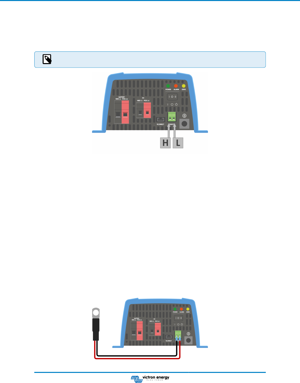
If an external battery sensor is used, connect the temperature sensor in the following way:
1. Connect the M10 cable lug part of the temperature sensor to one of the battery terminals.
2. Remove the wire loop from the REMOTE connector.
3. Connect the negative (black) wire to the H (left) terminal of the REMOTE connector.
4. Connect the positive (red) wire to the L (right) terminal of the REMOTE connector.
Connecting a battery temperature sensor to the REMOTE connector.
SUN Inverter Manual
Page 8 Installation
3.2.6. VE.Direct connection
The VE.Direct connection can be used for monitoring of the inverter via a GX device, or to connect to the VictronConnect app.
The following items can be connected:
• A GX device or GlobalLink 520 using a VE.Direct cable.
• A GX device using a VE.Direct to USB interface.
• A computer running the VictronConnect app using the VE.Direct to USB interface.
• A phone or tablet running the VictronConnect app using the VE.Direct Bluetooth Smart dongle.
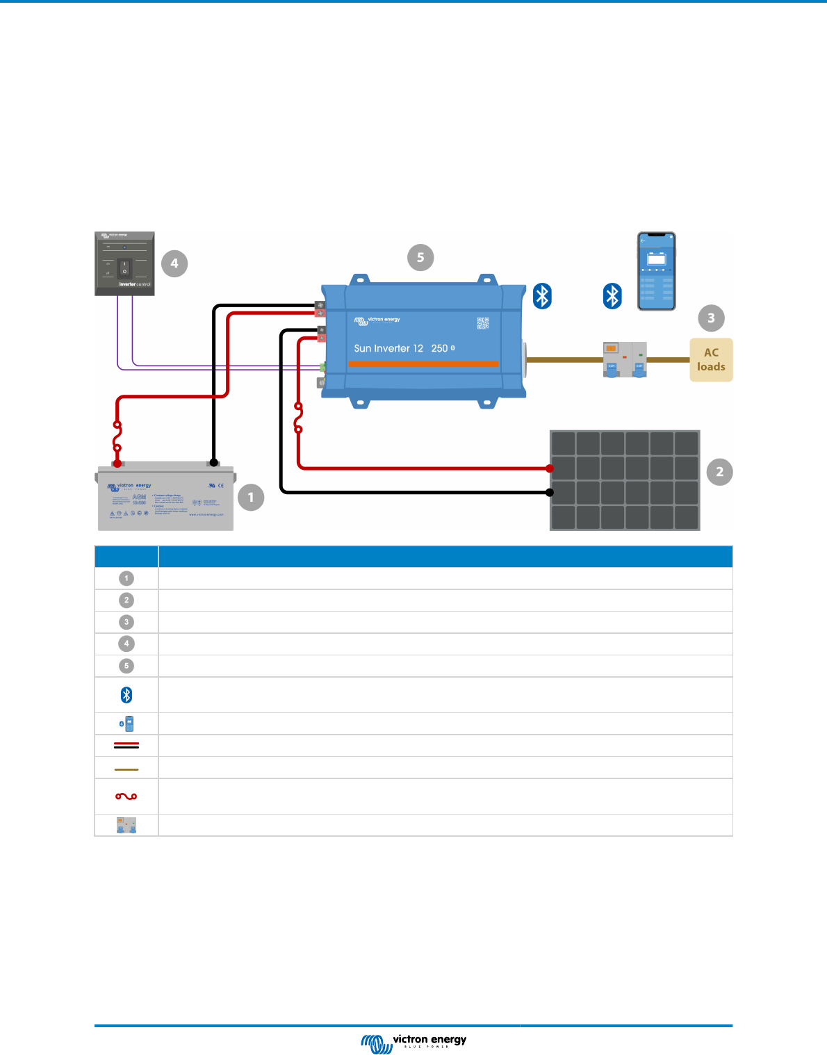
3.2.7. SUN Inverter system example
ID Item and notes
Battery
Solar array consisting of a single or multiple solar panels.
AC system.
Phoenix Inverter Control VE.Direct for on/off control of the inverter.
SUN inverter 12V 250VA
Bluetooth communication, use with the VictronConnect app for monitoring, configuration and inter-product
communication (VE.Smart Networking).
VictronConnect app to monitor and configure all Bluetooth enabled Victron "Smart" products.
Positive (red) and negative (black) DC wiring. For more information on wiring see the Wiring Unlimited book.
AC wiring.
DC fuse. A wide range of DC fuses and fuse holders are available from Victron Energy. For fuse ratings see the
product manuals or the Wiring Unlimited book.
Circuit breaker (MCB) and residual current device (RCD).
SUN Inverter Manual
Page 9 Installation
4. Configuration
The inverter is ready for use with the standard factory settings (see the Technical specifications [26] chapter).
The inverter can be configured using the VictronConnect app. Connect using a smartphone or tablet via Bluetooth or using a
computer via USB and a VE.Direct to USB interface).
• Settings may only be changed by a qualified engineer.
• Carefully read the instructions before changes are made.
4.1. AC output voltage and frequency
The inverter is set by default at 230Vac.
The AC output voltage and frequency can be set to a different value according to below table.
Model AC output voltage range Frequency range
230Vac models Between 210Vac and 245Vac 50Hz or 60Hz
4.2. ECO mode and ECO settings
The inverter is equipped with ECO mode. ECO mode is activated via the VictronConnect app.
When the inverter is in ECO mode, it will reduce its power consumption by approximately 85% when there are no loads
connected to the inverter.
When the inverter is in ECO mode, the inverter will switch to search state when there is no load or a very low load. While in the
search state, the inverter is off and will switch on every 3 seconds for a short period (adjustable). If the inverter detects a certain
size load (adjustable) the inverter will go back to normal operation mode. Once the load drops below a certain level, the inverter
will go back to ECO mode.
Below table indicates the default settings and setting range of the ECO parameters:
Parameter Default value Range
Wake-up minimum power 14VA 14VA - inverter rating
ECO mode search interval 3s 0 - 64s
ECO mode search time 0.16s 0.08 - 5.00s
• Note that the required ECO mode settings are heavily dependent on the type of load: inductive, capacitive,
non-linear. Adjustment for specific loads may be needed.
4.3. Low battery alarm and charge detect settings
The inverter has two different types of low battery shutdown modes:
• Low battery shutdown based on battery voltage. This is the "low battery shutdown" voltage.
• Low battery shutdown based on battery voltage as a function of battery load. This mode is disabled by default. See next
chapter Dynamic cut off [11] for more information.
Once the inverter has shut down due to a low battery (regardless of the mode):
• The inverter will restart again once the battery voltage has increased above the "low battery restart and alarm" level.
• The inverter will clear the low battery alarm once it detects the battery is being charged. This is the "charge detect" voltage.
Battery voltage Low battery shutdown Low battery restart & alarm Charge detect
12V
Default: 9.3V
Range: 0-100V
Default: 10.9V
Range: 0-100V
Default: 14V
Range: 0-100V
24V
Default: 18.6V
Range: 0-100V
Default: 21.8V
Range: 0-100V
Default: 28.0V
Range: 0-100V
SUN Inverter Manual
Page 10 Configuration

4.3.1. Dynamic cut off
The "Dynamic cut off" feature makes the low battery shutdown protection a function of the battery current drawn from the battery
in relation to the battery voltage.
When a high current is being drawn from the battery, a lower cut off voltage threshold is being used, for example 10V. And
similarly, when the battery is only being discharged slowly, a high cut off voltage is used, for example 11.5V.
In this way, a voltage drop, caused by the internal resistance in the battery, is compensated so that the battery voltage becomes a
much more reliable parameter to decide when to stop discharging the battery.
The "Dynamic cut off" feature is most useful for batteries with a high internal resistance, like OPzV and OPzS batteries. It is
a bit less relevant for GEL and AGM batteries and perhaps even irrelevant for lithium batteries. The below graph shows the
discharge ratio versus battery voltage curve for the different battery types. You can see that the lithium curve (LiFePO4) is nearly
flat compared to the OPzV and OPzS curve.
The curve can be adjusted in the VictronConnect app.
Discharge ratio versus battery voltage graph for different battery types
• Do not use the "Dynamic cut off" feature in an installation that also has other loads connected to the same
battery. In these systems the battery voltage might drop because of other loads connected to the battery.
The dynamic cut off algorithm in the inverter can not take those other loads into consideration and will shut
down the Inverter too early with an under voltage alarm.
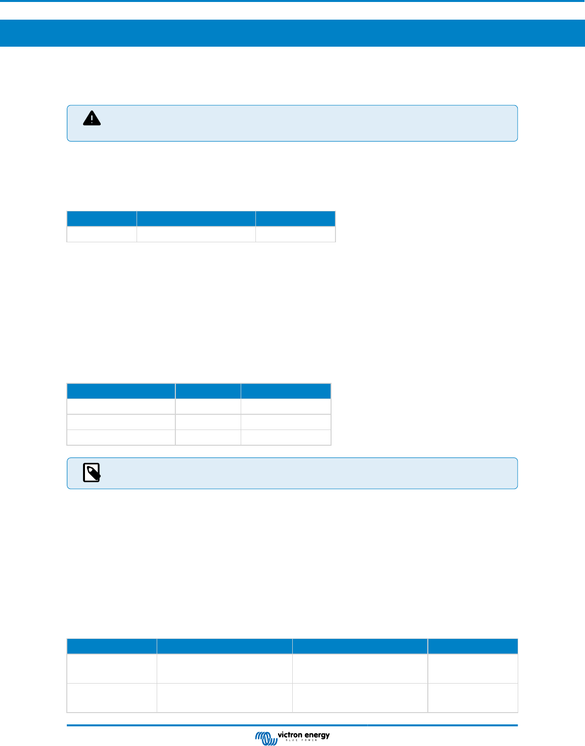
VictronConnect settings
• The "Dynamic cut off" feature is disabled by default.
• Enable the "Dynamic cut off" feature to use and configure it.
• Select the battery type. Choose between: OPzV/OPzS, GEL/AGM, LiFePO4 or Custom.
• Enter the battery capacity.
• Enter the voltage for the various discharge currents. These values have already been set to the generic voltages that belong to
the specific battery type that was selected earlier. Change these settings only in case they need adjustment
and you know what
you are doing, or in case a custom battery is being used.
SUN Inverter Manual
Page 11 Configuration
VictronConnect app showing the "Dynamic cut off" settings
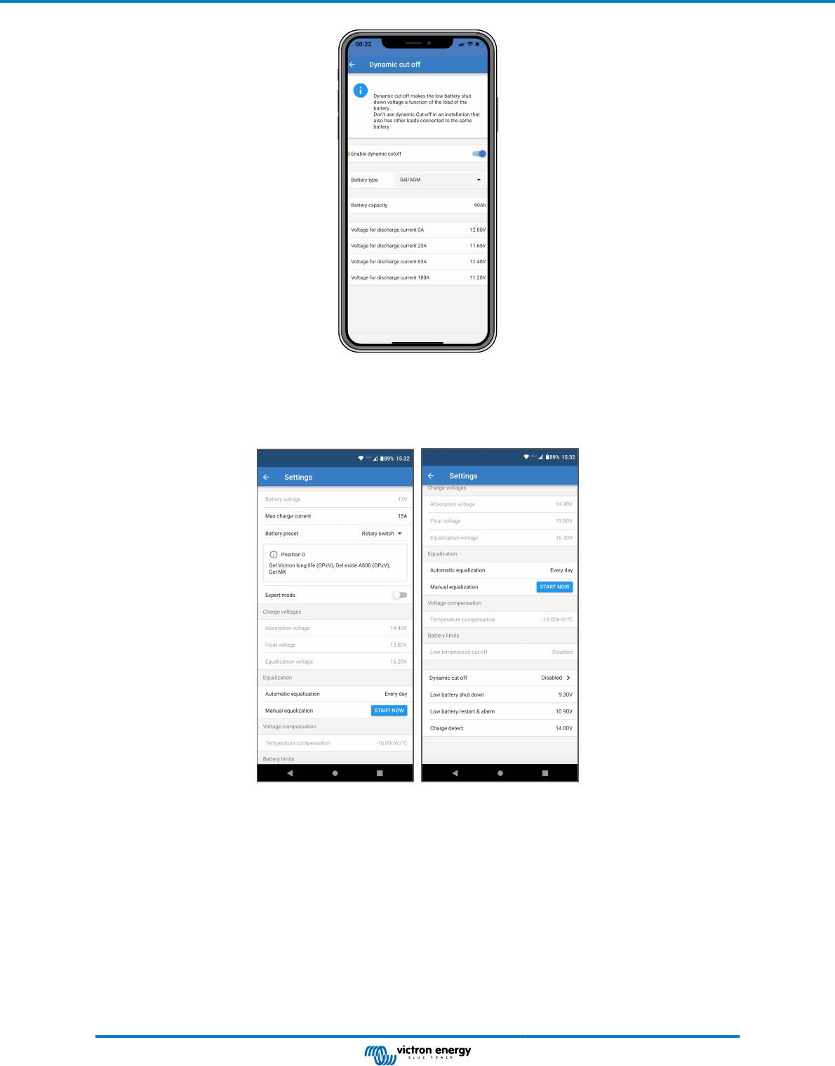
4.4. Battery settings
Max charge current
This setting sets the maximum battery charge current. It is by default set to the maximum solar charge current.
Use this setting to reduce the charge current, for example, when a smaller battery bank is used that requires a lower charge
current.
Battery preset
This setting sets the battery charge algorithm.
A selection can be made between:
• Pre-defined factory battery presets
• User-defined battery presets
• Create, modify or delete a user-defined preset.
SUN Inverter Manual
Page 12 Configuration
This setting uses factory pre-defined presets for a large variety of battery types. These pre-defined charge algorithms are suitable
for almost all installations.
It is possible to also create user-defined battery presets. The chapter Customize battery charge algorithm explains how to do this.
These user-defined presets are stored in the VictronConnect app library. This is helpful in case multiple solar chargers need to be
configured, eliminating the need to define the entire charge algorithm each time a new solar charger is configured.
Expert mode
This setting enables or disables expert mode. It is by default set to "disabled".
The default charge algorithms work well for almost all installations. Only enable expert settings if your
equipment has special requirements.
When this setting is enabled the following parameters can be configured:
• Charger voltages: bulk, absorption and float
• Bulk: re-bulk voltage offset
• Absorption: duration, time and tail current
• Equalization: current, interval, stop mode and duration
• Temperature voltage compensation
• Low temperature cut off
For the meaning of these parameters see chapter Battery charge algorithm settings [13]
Equalization
Equalization can cause damage to the battery if the battery is not suitable for an equalization charge. Always
check with the battery manufacturer prior to enabling equalization.
This setting can be used to disable or enable automatic equalization. When enabled, the number of days can be selected when
equalization should repeat.
A manual equalization can be initiated by pressing the "START NOW" button. Use the manual equalize option only during
absorption and float charge stages, and when there is sufficient sunlight. The current and voltage limits are identical to the
automatic equalize function. The manual equalization stage lasts 1 hour and can be stopped at any time by the Stop Equalize.
The equalization setting might not be active, this can be the case if the battery preset does not support an
equalization charge which is the case with lithium batteries.
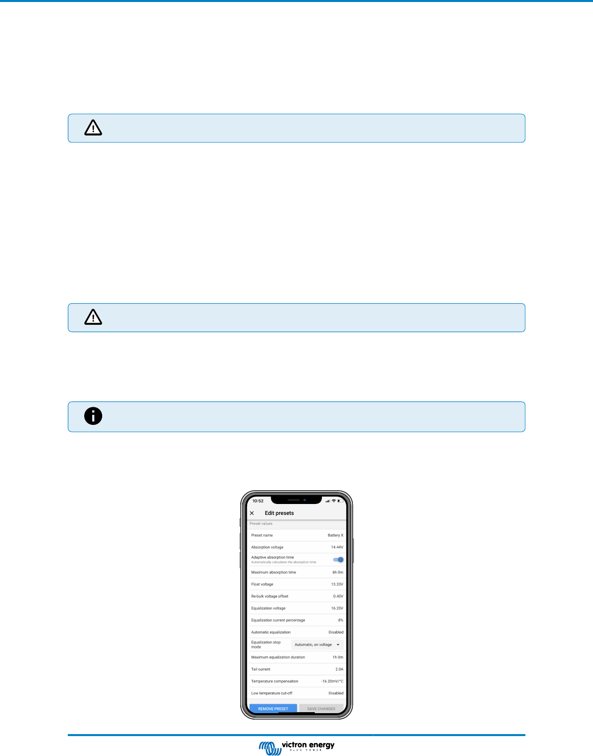
4.4.1. Battery charge algorithm settings
This chapter explains all parameters that are used in "Expert" mode and the settings that are used when programming a custom
battery type via the battery preset menu.
SUN Inverter Manual
Page 13 Configuration
Absorption voltage
This setting sets the absorption voltage.
Adaptive absorption time
This setting enables or disables the adaptive absorption time.
• When disabled: The length of the absorption stage is the same each day, the length is determined by the "Maximum
absorption time" setting, provided there is enough solar power.
Be aware that this option can potentially result in overcharging your batteries, especially for lead batteries and if only shallow
daily discharges take place. Check with the battery manufacturer for the recommended maximum absorption time.
The only condition that can end the absorption time before the maximum time has been reached, is the "tail current" setting. If
the absorption time always needs to be the same length, then disable the "Tail current" setting. See more information on the tail
current setting further down in this chapter.
• When enabled: The length of the absorption stage is different each day, it adapts itself to the state of charge of the battery in
the morning at the beginning of the charge cycle.
The maximum "adaptive" absorption time for the day is determined by the battery voltage as measured just before the solar
charger begins operation each morning.
Multiplier x 1 x 2/3 x 1/3 x 1/6
Adaptive absorption
time *
6:00 hours 4:00 hours 2:00 hours 1:00 hour
12V system Vbatt < 11.9V
11.9V < Vbatt <
12.2V
12.2V < Vbatt <
12.6V
Vbatt > 12.6V
24V system Vbatt < 23.8
23.8 < Vbatt <
12.2V
24.2V < Vbatt <
25.2V
Vbatt > 25.2V
*) The adaptive absorption time is calculated by the multiplier times the "Maximum absorption time" setting. The adaptive
absorption times in this table are based on the 6 hour default "Maximum absorption time" setting.
Maximum absorption time
This setting sets the absorption time limit. This setting is only available when programming a custom charge profile.
Enter the maximum time in hours and minutes (hh:mm) the solar charger is allowed to spend in the absorption stage. The
maximum time that can be set is 12 hours and 59 minutes.
Float voltage
This setting sets the float voltage.
Re-bulk voltage offset
This setting sets the re-bulk voltage offset. This offset voltage is used to determine when a charge stage stops and the bulk stage
starts again, i.e. the charge cycle resets and starts at the first charge stage again.
The re-bulk voltage is calculated by adding the re-bulk voltage offset to the lowest voltage setting (normally this is the float stage).
An example: If the re-bulk offset is set at 0.1V and the float voltage at 13.8V, the charge cycle will restart once the battery voltage
drops below 13.7V (13.8 minus 0.1) for one minute.
Equalization voltage
This setting set the equalization voltage.
Equalization current percentage
This setting sets the percentage of the "maximum charge current" setting that will be used to calculate the equalization charge
current.
For example: If the "maximum charge current" setting is set at 10A and the "Equalization current percentage" setting is set to
10%, the Equalization current will be 1A (10% of 10A).
Automatic equalization
This setting sets the repeat interval when the equalization stage should take place. This can be set between 1 and 250 days.
Setting to 1 means a daily equalization, 2 means every other day and so on.
An equalization stage is typically used to balance the cells and also to prevent stratification of the electrolyte in flooded lead-acid
batteries. If equalization is needed or not depends on the type of battery if (automatic) equalization is needed and under what
conditions. Check with the battery supplier to find out if equalization is needed for the battery.
During the equalization stage, the charge voltage increases up to the set "Equalization voltage". This is maintained as long as the
charge current stays below the "equalization current percentage" setting of the "Maximum current" setting.
SUN Inverter Manual
Page 14 Configuration
Duration of the Automatic equalization cycle:
• For all VRLA battery presets and for some flooded battery presets, the automatic equalization stage ends when the voltage limit
(maxV) has been reached.
• For the lithium battery preset, equalization is not available.
• When an automatic equalization stage has not been completed within one day, it will not resume the next day. The next
equalization surge will take place according to the interval as set in the "Auto Equalization" setting.
Equalisation stop mode
This setting determines when the equalisation stage should end:
• Automatic: Equalization stops if the battery voltage has reached the equalisation voltage
• Fixed time: Equalization stops when the time has reached the time as set in the "Maximum equalization duration" setting.
Maximum equalization duration
This setting sets the maximum time that the equalization stage will last.
Manual equalization
Use this to perform a "once-off" equalization. Once the "start now" button is pressed, a one-hour equalization cycle will be
performed, alternatively, the equalization stage can be stopped manually.
Tail current
This setting sets the current threshold to end the absorption stage before the maximum absorption time has been reached. If the
charge current drops below the set tail current, for one minute, the absorption stage will end and the float stage will start. This
setting can be disabled by setting it to zero.
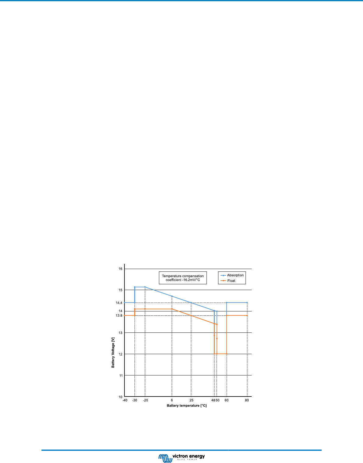
Temperature compensation
This setting sets the temperature compensation coefficient that is needed for temperature compensated charging.
Many battery types require a lower charge voltage in warm operating conditions and a higher charge voltage in cold operating
conditions. The configured coefficient is in mV per degree Celsius for the whole battery bank, not per cell. The base temperature
for the compensation is 25°C (77°F).
The chart below indicates the absorption and float charge voltage behaviour at different temperatures. The graph displays the
temperature compensation for a 12V system and uses a -16mV/°C temperature compensation coefficient. For a 24V system
multiply the voltages by 2.
Temperature compensated charge graph
By default, the SUN Inverter uses its internal temperature for battery temperature compensated charging. An internal temperature
reading is taken in the morning and then again when the e SUN Inverter has been idle for at least one hour, for example when the
charger is not actively charging a battery or supplying a load.
SUN Inverter Manual
Page 15 Configuration

When the SUN Inverter is part of VE.Smart Networking and receives a battery temperature reading from a Battery Sense or a
battery monitor with a temperature sensor, the actual battery temperature will be used for temperature compensated charging
throughout the day.
Low temperature cut-off
This setting is used to prevent damage to a lithium battery by disabling charging at low temperatures.
The "Low temperature cut-off" feature is only active when a temperature sensor is connected. See the
Temperature sensor [4] chapter for more information.
The "low temperature cut-off" setting is by default disabled. When enabled, a low cut off temperature can be set. The default
temperature is 5°C, this is a suitable temperature setting for lithium iron phosphate (LFP) batteries. However, always check with
the lithium battery supplier to find out what this temperature should be set at.
The "low temperature cut-off" mechanism will stop battery charging when the battery temperature has dropped below the low
temperature cut-off setting. Battery charging will resume once the battery temperature has risen 0.5°C above the low temperature
cut-off setting.
Note that setting "low temperature cut-off" is not needed for Victron Lithium Smart batteries or for Victron Super Pack batteries
with serial number HQ2040 and above. This setting is only needed for lithim batteries that are unable to block charging when the
temperature drops too low.
4.5. VE.Smart Networking
The VE.Smart Networking allows a variety of products connected to the same network to share data via Bluetooth. The VE.Smart
Networking is especially designed for smaller systems that do not have a GX device installed.
When this product is part of a VE.Smart Networking it can receive data or communicate with the following devices:
• All SmartSolar solar chargers
• All BlueSolar solar chargers that are connected to a VE.Direct Bluetooth Smart dongle.
• The Smart Battery Sense
• A BMV or SmartShunt battery monitor equipped with Bluetooth (or VE.Direct Bluetooth Smart dongle) and a optional BMV
temperature sensor.
• Certain AC chargers
• SUN inverter
For the product compatibility list see the VE.Smart manual located on the VictronConnect app product page.
The VE.Smart Networking can be used for:
• Temperature sensing - the measured battery temperature is used by the chargers in the network for temperature compensated
charging and in case of lithium battery for the low temperature cut off.
SUN Inverter Manual
Page 16 Configuration
• Battery voltage sensing - the measured battery voltage is used by the chargers in the network to to compensate the charge
voltage should there be a voltage drop over the battery cables.
• Current sensing - The measured battery current is used by the charger so it knows the exact tail current at which the absorption
stage should end and the float (or equalisation) stage should start. To measure the charge current all charge currents from all
chargers are combined, or if a battery monitor is part of the network the actual battery current will be used.
• Synchronised charging - All chargers in the network will act as they were one large charger. One of the chargers in the network
will assume a master role and the master will dictate the charge algorithm the other chargers will be using. All chargers will
follow the same charge algorithm and charge stages. The master is selected randomly (not user settable) so it is important
that all chargers use the same charge settings. During synchronised charging each charger will charge up to its own maximum
charge current setting (it is not possible to set a maximum current for the whole network). For more information see the
VE.Smart manual located on the VictronConnect app product page.
This video introduces the Smart Battery Sense and some features of the VE.Smart Networking:
https://www.youtube.com/embed/v62wCfXaWXY
4.5.1. VE.Smart Networking setup
VE.Smart Networking design notes:
There can only be one product in the network that transmits battery voltage and/or battery temperature. It is not possible to use a
battery monitor together with a Smart Battery Sense, or multiples of these devices.
For the network to be operational all networked devices must be within Bluetooth transmission distance of each other.
A maximum of 10 devices can be joined into a VE.Smart Networking.
Some older devices might not support VE.Smart Networking. for more information see the Limitations chapter in the VE.Smart
Networking manual.
Setting up the network
When setting up the network, first set up the Smart Battery Sense or battery monitor, and then add one or more solar chargers or
AC chargers to the network.
All solar chargers and AC chargers need to have the same charge settings. The easiest way to do this is to use a preset battery
type or a saved used defined battery type. A warning #66 message will be shown if there is a difference between the devices
charge settings.
To set up a new network:
• Open the VictronConnect app.
• Select one of the devices that needs to become part of the new VE.Direct network.
• Navigate to the settings page by clicking the gear symbol.
• click on "VE.Smart networking".
• Click on "create network".
• Enter a name for the new network.
• Click "save".
• Wait for confirmation that the network has been set up and click "OK".
• If more devices need to be added to this network go to next paragraph and join multiple devices to the network.
To join another device to an existing network:
• Open the VictronConnect app. Select a device that needs to become part of a VE.Direct network.
• Navigate to the settings page by clicking the gear symbol.
• Click on "VE.Smart Networking".
• Click on "join existing".
• Select the network the device needs to be joined to.
• Wait for confirmation that the network has been set up and click "OK".
• Repeat above steps if more devices need to be added to the network.
To leave a network:
SUN Inverter Manual
Page 17 Configuration
• Open the VictronConnect app.
• Select a device that needs to be removed from the VE.Direct network.
• Navigate to the settings page by clicking the gear symbol.
• Click on "VE.Smart Networking".
• Click on "leave network".
Check the network
Once the network has been set up all devices communicate with each other. The active LED on each connected device will now
blink every 4 seconds. This is an indication that the device is actively communicating with the network.
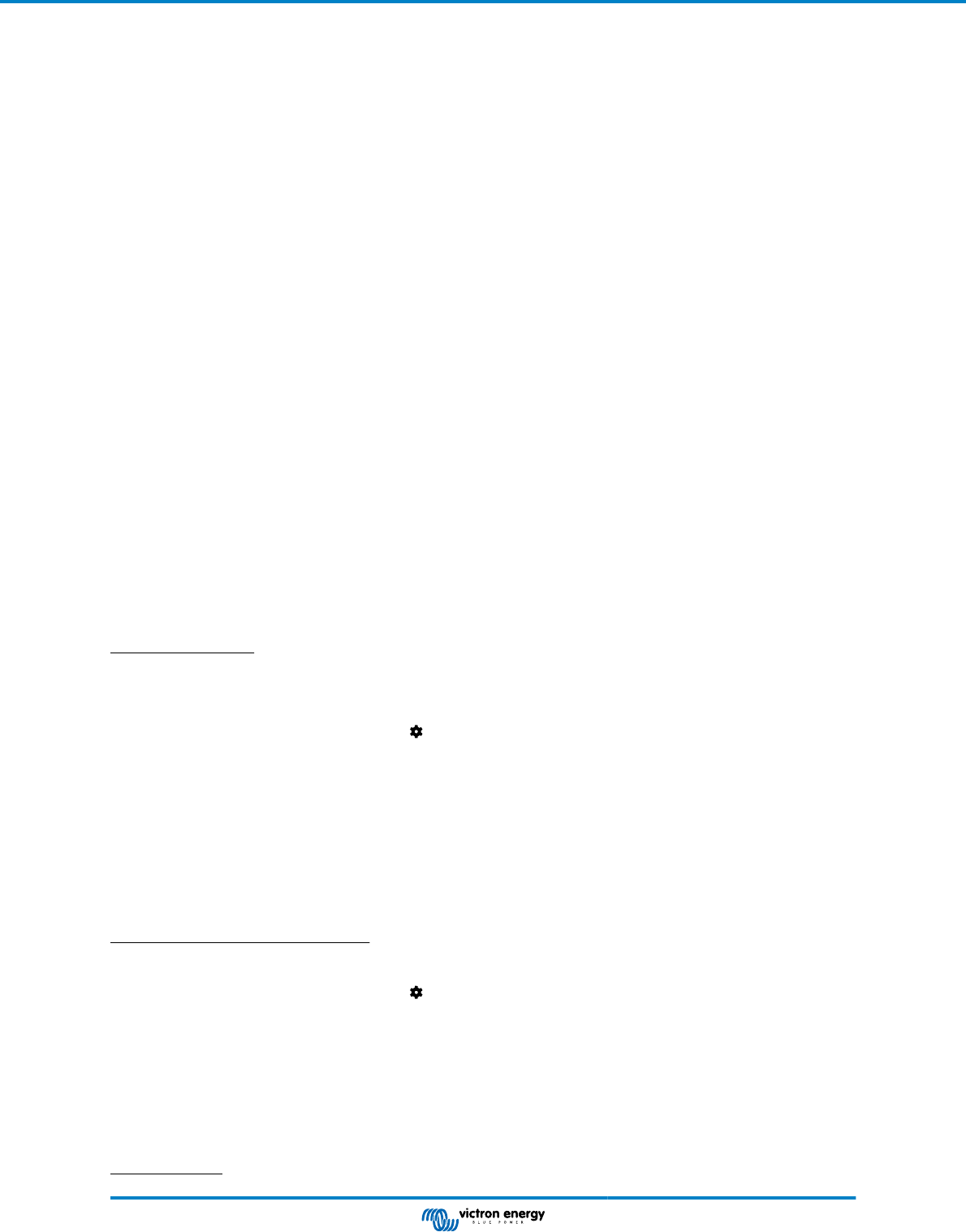
To check if an individual device is communicating with the network, click on the VE.Smart symbol in the main screen next to
the solar dail. A pop-up window will open showing the connection status and the shared parameters.
VE.Smart Networking pop-up
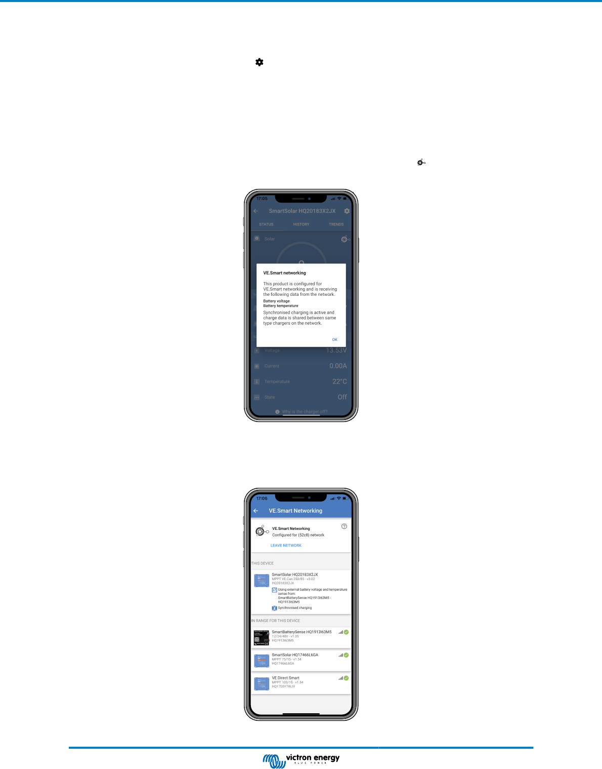
To check if all devices are actively communicating with the same VE.Smart Networking, navigate to the settings page of one of
the networked devices and click on "VE.Smart Networking". A screen will be shown containing which device parameters of this
device are shared and all the other devices that are connected to the same network are shown.
Example of a VE.Smart Networking
SUN Inverter Manual
Page 18 Configuration

More information
For more information see the VE.Smart Networking manual.
4.6. Firmware update
The firmware can be updated in the inverter product settings:
• Navigate to the inverter settings by clicking on the cog
symbol in the right top corner.
• Click on the 3 dot
symbol in the right top corner.
• Choose "Product settings" from the menu.
• The firmware section will display the firmware version and a button to perform a firmware update.
4.7. Reset settings to default
The inverter settings can be set to default in the following way:
• Navigate to the inverter settings by clicking on the cog
symbol in the right top corner.
• Click on the 3 dot symbol in the right top corner.
• Select "Reset to defaults" from the menu and the settings will reset to default.
SUN Inverter Manual
Page 19 Configuration
5. Operation
5.1. Inverter
The inverter can be turned on via these methods:
• ON/OFF/CHARGER-ONLY switch.
• The VictronConnect app.
• Remote terminal with wire loop.
• Remote switch connected to the remote terminal (optional).
• Phoenix Inverter Control VE.Direct panel connected to the remote terminal (optional).
• A GX device and the VRM portal (optional).
5.1.1. ECO Mode
The inverter can be switched to ECO mode, via the VictronConnect app.
When the inverter is running in ECO mode it reduces power consumption in no-load (standby) operation. The inverter will
automatically switch off as soon as it detects that there is no load connected. It then switches on, briefly, every 3 seconds to
detect a load. If the output power exceeds the set level, the inverter will continue to operate.
For more information about ECO mode, see the ECO mode and ECO settings [10] chapter.
5.2. Solar charger
The solar charger is active as soon as the switch is switched to ON or to CHARGE. The solar charger will start charging the
batteries as soon as the solar panel voltage is higher than the battery charger voltage.
The charge algorithm is a 3-stage charge algorithm, similar to that in our other chargers and solar chargers:
Bulk charge stage
The battery is charged at maximum charge current until the voltage increases to the configured absorption voltage. The bulk
stage duration is dependent on the battery’s level of discharge, the battery capacity and the charge current. Once the bulk stage
is complete, the battery will be approximately 80% charged (or >95% for lithium batteries) and may be returned into service if
required.
Absorption charge stage
The battery is charged at the configured absorption voltage, with the charge current slowly decreasing as the battery approaches
full charge. The absorption stage duration is adaptive and intelligently varied depending on the battery’s level of discharge – this
is determined from the duration of the bulk charge stage. The absorption stage duration can vary between a minimum of 30
minutes, up to a maximum limit of 8 hours (or as configured) for a deeply discharged battery.
Float charge stage
The battery voltage is maintained at the configured float voltage. Once float stage is commenced, the battery is fully charged and
ready for use. If the battery is unused, the charger can remain connected to the battery and the float stage will prevent discharge
due to the battery's self-discharge.
5.2.1. CHARGE mode
The inverter can be switched to CHARGE mode via its "ON/OFF/CHARGE" switch.
When in CHARGE mode, the inverter is turned off and only the solar charger is operational. This mode ensures that the battery
remains charged from solar power, while AC loads can not discharge the battery, providing the solar panel voltage is higher than
the battery voltage.
Use this mode, for example, when the AC loads are not in use or when the installation is not attended.
5.3. Power and Alarm LED definitions and troubleshooting
SUN Inverter Manual
Page 20 Operation
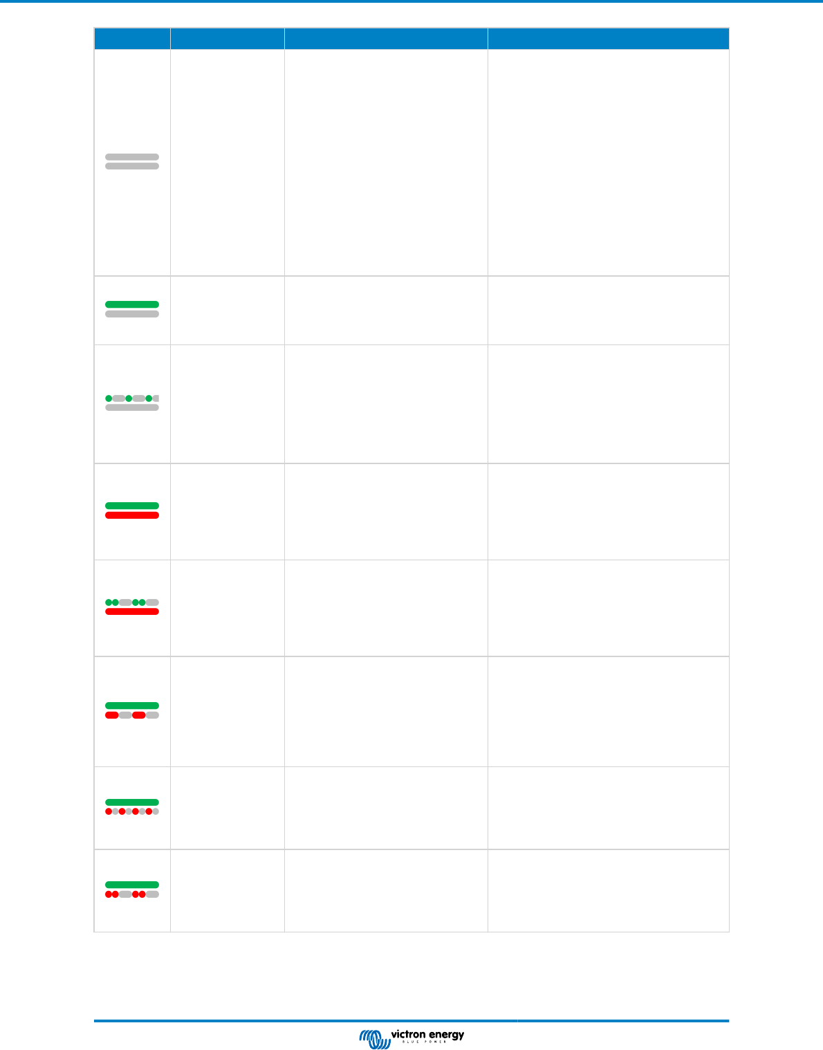
LEDs LED behaviour Operational mode Troubleshooting
Green POWER
LED off.
Red ALARM LED
off.
The inverter has been switched off,
either directly or via its remote on/off
connector, or the inverter is not
powered.
Check the ON/OFF/ECO switch: it should
be in ON position or in ECO position.
To check if the inverter is operational, turn
the switch to OFF and then to ON.
If not operational, check the following:
• Check the remote on/off connector. Is the
wire loop in place or is the remote switch
or remote panel switched on?
• Check the DC cable connections and
external fuses. Do you measure battery
voltage at the inverter battery connection?
• If the internal fuse is blown, the inverter
has to be returned for service.
Green POWER
LED on.
Red ALARM LED
off.
The inverter has been switched on
and is operational.
n/a
Green POWER
LED blinking slow
with a short pulse.
Red ALARM LED
off.
The inverter has been switched to
ECO mode and is in "search" state.
In other words, the inverter load is
lower than the "Wake up power"
setting. the inverter sends a search
pulse at regular intervals to check if
a load has been connected or has
been turned on.
If the inverter keeps switching on and off
while there is a load connected, the load
may be too small compared to the actual
ECO mode settings. Either increase the
load or change the "wake up power" setting.
Green POWER
LED on.
Red ALARM LED
on.
Overload warning.
The inverter is indicating that the AC
load is larger than the inverter rating
and that if this situation continues,
the inverter will switch off due to an
overload alarm
Reduce the AC load
Green POWER
LED blinking with
a fast double
pulse.
Red ALARM LED
on.
Overload alarm.
The inverter has shut down due
to prolonged overload and will no
longer automatically restart.
Remove the cause of the overload and then
restart the inverter by switching it off and
then back on again.
For more information also see the
Protections and automatic restarts [23]
chapter.
Green POWER
LED on.
Red ALARM LED
blinking slow.
Low battery voltage warning.
The battery voltage has dropped
below the "Low battery alarm"
voltage. Should the battery voltage
drop any further, the inverter will
switch off on a "Low battery voltage
alarm".
Charge the battery and/or turn AC loads off.
Also check if all battery cable connections
have been tightened. Do the battery cables
have a sufficient thickness, is the battery
full and is the battery still in good working
order?
Green POWER
LED on.
RED ALARM LED
blinking fast.
High Battery voltage warning.
The battery voltage is too high.
Should the battery voltage increase
any further, the inverter will switch
off on a "High battery voltage alarm".
Reduce the DC input voltage, check if the
battery voltage is correct and if the battery
bank is wired correctly. Also check if there
perhaps are faulty or incorrect chargers or
equipment with a faulty charge regulator.
Green POWER
LED on.
Red ALARM LED
blinking with a fast
double pulse.
High temperature warning.
The internal temperature is too high.
If the temperature increases any
further, the inverter will switch off on
a "High temperature alarm".
Reduce the AC load and/or move the
inverter to a better ventilated area.
SUN Inverter Manual
Page 21 Operation
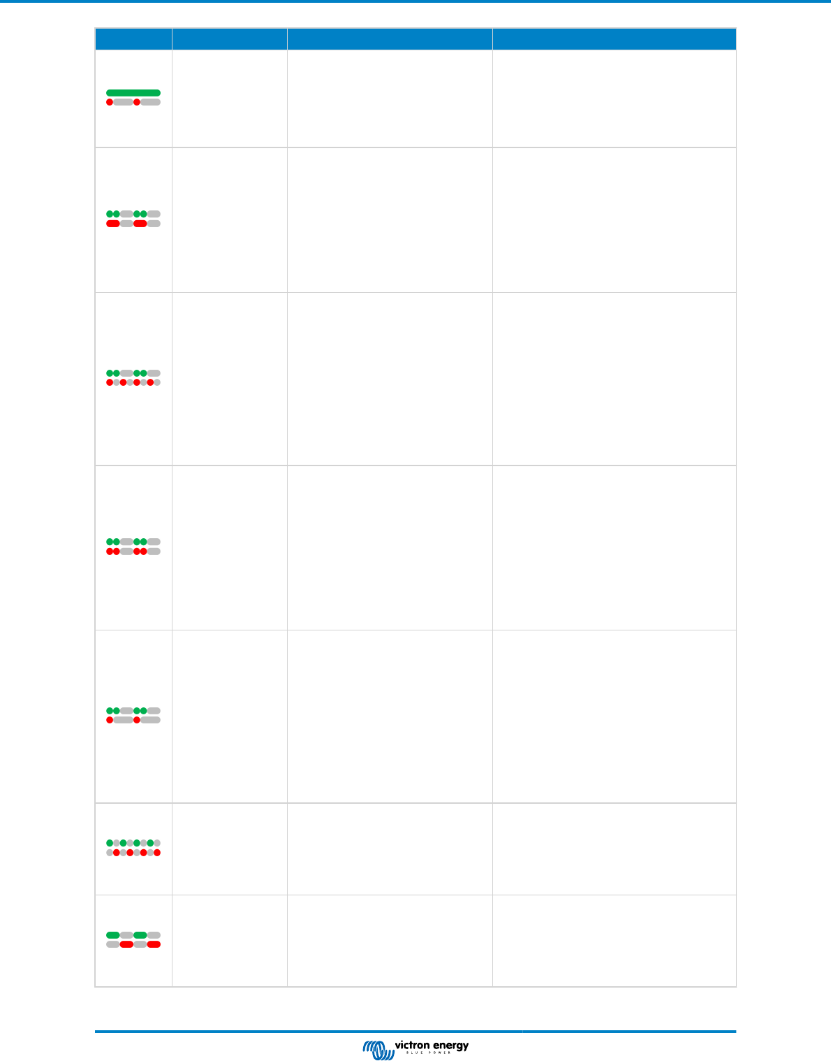
LEDs LED behaviour Operational mode Troubleshooting
Green POWER
LED on.
Red ALARM LED
blinking with a fast
single pulse at
longer intervals.
High DC ripple warning.
The DC voltage has a too high
ripple voltage. If the ripple voltage
increases any further, the inverter
will switch off on a "High DC ripple
alarm".
Check if all battery cable connections have
been tightened. Do the battery cables have
a sufficient thickness? DC ripple is related to
a voltage drop over the battery cables. For
more information on DC ripple and how to
prevent it, see the Wiring Unlimited book.
Green POWER
LED blinking with
a fast double
pulse.
Red ALARM LED
blinking slow.
Low battery voltage alarm.
The inverter has shut down due to
low battery voltage.
To restart the inverter, charge the battery
or switch the inverter off and then back on
again.
Check the battery voltage at the battery
terminals of the inverter. Also check the DC
fuses, cables, and cable connections
For more information also see the
Protections and automatic restarts [23]
chapter.
Green POWER
LED blinking with
a fast double
pulse.
RED ALARM LED
blinking fast.
High battery voltage alarm.
The inverter has shut down due to
high battery voltage.
Reduce the DC input voltage, check if the
battery voltage is correct and if the battery
bank is wired correctly. Also check if there
perhaps are faulty or incorrect chargers or
equipment with a faulty charge regulator.
The inverter will automatically turn back on
when the battery voltage has dropped to an
acceptable level.
For more information also see the
Protections and automatic restarts [23]
chapter.
Green POWER
LED blinking with
a fast double
pulse.
Red ALARM LED
blinking with a fast
double pulse.
High temperature alarm.
The inverter has shut down due to
high temperature.
Wait until the inverter has cooled down.
The inverter will automatically turn back on
when its internal temperature has dropped
to an acceptable level.
Check the environment of the inverter, can
the ventilation be improved, or can the
inverter be moved to a cooler location?
For more information also see the
Protections and automatic restarts [23]
chapter.
Green POWER
LED blinking with
a fast double
pulse.
Red ALARM LED
blinking with a fast
single pulse at
longer intervals.
DC ripple alarm.
The inverter has shut down due to
high DC ripple.
Check if all battery cable connections have
been tightened. Do the battery cables have
a sufficient thickness? DC ripple is related to
a voltage drop over the battery cables. For
more information on DC ripple and how to
prevent it, see the Wiring Unlimited book.
To restart the inverter switch the inverter off
and then back on again.
For more information also see the
Protections and automatic restarts [23]
chapter.
Green POWER
LED and red
ALARM LED
blinking fast in
an alternating
fashion.
Firmware update active.
Wait until the update has been finalized.
If the firmware update fails retry the
firmware update.
Green POWER
LED and red
ALARM LED
blinking slow in
an alternating
fashion.
Calibration or parameter error. Contact your Victron supplier for support.
SUN Inverter Manual
Page 22 Operation
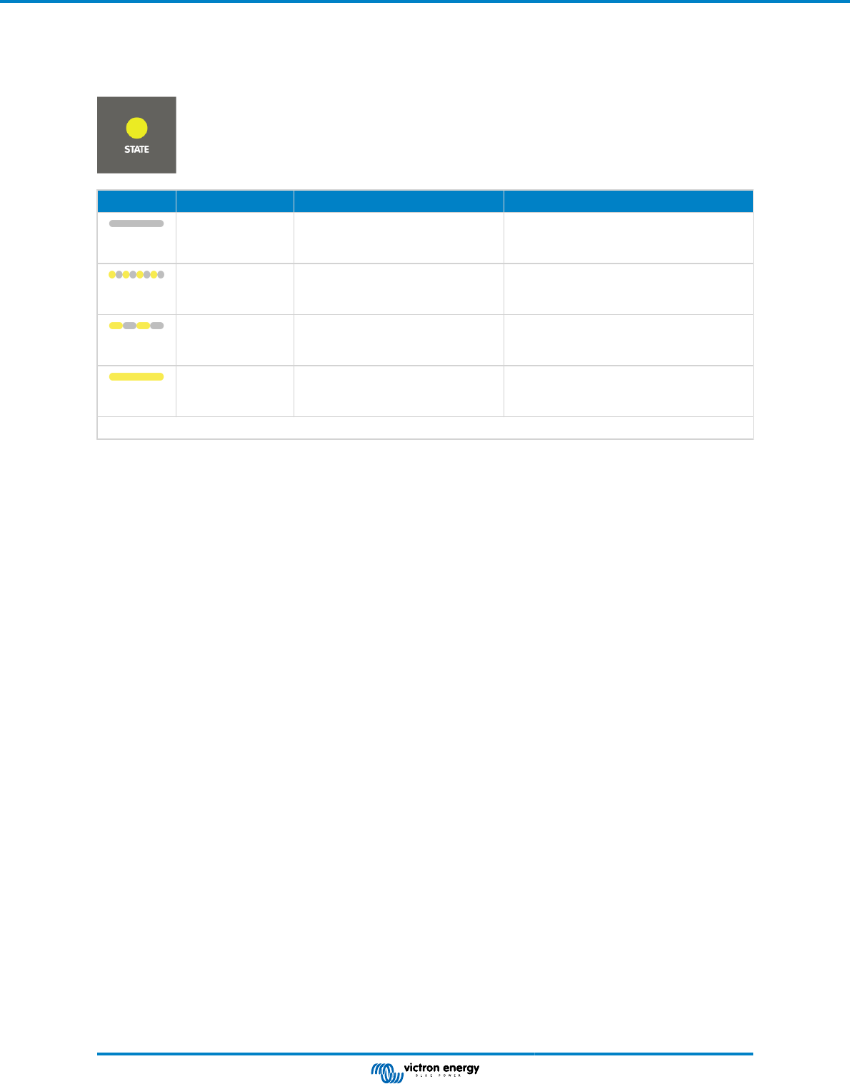
5.4. STATE LED definitions
The yellow STATE LED indicates the state of the solar charger. This LED operates independently from the POWER LED and the
ALARM LED.
LED LED behaviour Operational mode Battery
Yellow STATE
LED off.
The solar charger is switched off, or
there is not enough solar power to
charge the battery.
The battery is not being charged by the
SUN inverter.
Yellow STATE
LED blinking fast.
The solar charger is charging the
battery and is in the bulk stage*.
This is the first part of the charge cycle. The
battery has a state of charge between 0%
and 80%.
Yellow STATE
LED blinking slow.
The solar charger is charging the
battery and is in the absorption
stage*.
This is the second part of the charge cycle.
The battery has a state of charge between
80% and 100%.
Yellow STATE
LED on.
The solar charger is charging the
battery and is in the float stage*.
This is the final part of the charge cycle. The
battery is full. The charge voltage has been
reduced.
*) For an explanation of the charging algorithm, see the Solar charger [20] chapter.
5.5. Protections and automatic restarts
Overload
Some loads like motors or pumps draw large inrush currents in a start-up situation. In such circumstances, it is possible that
the start-up current exceeds the over current trip level of the inverter. In this case the AC output voltage will quickly decrease to
limit the output current of the inverter. If the over current trip level is continuously exceeded, the inverter will shut down, wait 30
seconds and then restart.
After 3 restarts, followed by another overload within 30 seconds of restarting, the inverter will shutdown and remain off. The LEDs
will signal shutdown due to overload. To restart the inverter, switch it off and than back on again.
Low battery voltage (adjustable)
The inverter will shut down when the DC input voltage drops below the "Low battery shutdown" parameter. The LEDs will signal
shutdown due to low battery. The inverter will automatically restart, after a minimum delay of 30 seconds, when the battery
voltage has increased above the "Low battery restart" parameter.
After three restarts, followed by another low battery shutdown within 30 seconds of restarting, the inverter will shutdown and
remain off. The LEDs will signal shutdown due to low battery. To restart the inverter, switch it off, and then on again. Alternatively,
recharge the battery. The inverter will automatically restart when the battery voltage has increased for at least 30 seconds above
the "Charge detect" parameter.
See the Technical specifications [26] chapter for default low battery shutdown and restart levels. The levels can be customized
via the VictronConnect app.
Alternatively, a dynamic low battery cut off can be implemented. For more information, see the Dynamic cut off [11] chapter.
High battery voltage
The inverter will shut down when the DC input voltage is too high. The LEDs will signal shutdown due to high battery. The inverter
will first wait 30 seconds and will only resume operation once the battery voltage has dropped to an acceptable level.
Check for faulty battery chargers, alternators or solar chargers connected to the battery.
High temperature
The inverter will shut down if it detects a too high internal temperature. The LEDs will signal shutdown due to high temperature.
The inverter will wait 30 seconds and will only resume operation when the temperature has dropped to an acceptable level.
High temperature alarms are generally caused by a too high ambient temperature, often in combination with a high inverter load.
Check if the area the inverter is used in, is well ventilated and perhaps even air-conditioned.
High DC ripple
SUN Inverter Manual
Page 23 Operation
The inverter will shut down if it detects a too high DC ripple. The LEDs will signal shutdown due to high DC ripple. The inverter
will wait 30 seconds and then resumes operation again. If after 3 restarts, the DC ripple voltage is still too high, the inverter will
shutdown and will not attempt to restart again. To restart the inverter, switch it off and then switch it on again.
High DC ripple is usually caused by loose DC cable connections and/or too thin DC wiring. To clear or prevent ripple alarms,
check the wiring between the battery and the inverter. Check if the wiring is the recommended thickness, that all connections are
tightened correctly and that the fuses and battery isolators are in good working order. For more information on DC ripple see the
Wiring Unlimited book.
Continuous high DC ripple reduces the life expectancy of the inverter.
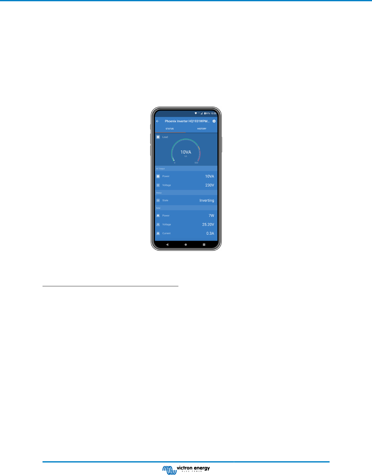
5.6. Monitoring via VictronConnect
The VictronConnect app can be used to monitor the inverter.
VictronConnect app.
For information on how to connect see the The VictronConnect app [3] chapter and/or the VictronConnect manual which can be
found on the VictronConnect app information page.
The VictronConnect app will display the following information:
• Inverter load as a percentage of the inverter rating.
• AC output voltage.
• Battery voltage.
• Operational state.
• Warning or alarm messages *.
• Solar power.
• Solar voltage.
• Solar current **.
• Solar open circuit voltage **.
*) Please note that the app is not active in the background. This means that the app will not send alarms or warnings to your
phone unless the app is active in the foreground.
**) The "open circuit voltage" is the solar panel voltage when no current is pulled from the panel. In situations where the open
circuit voltage is lower than the battery voltage, the solar current cannot be measured and as a result of this, the VictronConnect
app will indicate that the open circuit voltage is not available. The same is the case if the solar charger is in the bulk stage or
at the beginning of the absorption stage. The reason is that all solar power goes into the battery and the open solar voltage
effectively becomes the battery voltage. Only during a charge stage like at the end of absorption or float stage, where only little
current is required, the hardware can measure the "open circuit voltage".
SUN Inverter Manual
Page 24 Operation
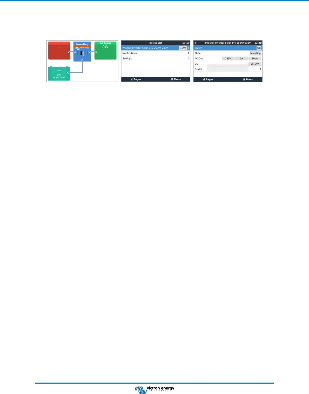
5.7. Monitoring via a GX device, GlobalLink and the VRM portal
The inverter can be connected to a GX device, like a Cerbo GX or a Color Control GX. When connected the GX device will
display the inverter on the system overview screen and the device list. The GX device will also display a message in case of an
inverter warning or alarm.
Example of GX screens from left to right: system screen, device list and inverter device screen.
If the GX device is connected to the internet, the inverter can be remotely monitored via the VRM portal. For more information on
the VRM portal, see the VRM - Remote monitoring information page.
Alternatively, the inverter can be connected to a GlobalLink 520, and then remotely monitored via the VRM portal.
SUN Inverter Manual
Page 25 Operation
6. Technical specifications
6.1. Technical specifications SUN Inverter
SUN Inverter 12/250 24/250
INVERTER
Continuous power at 25°C
(1)
250 VA
Continuous power at 25°C 200 W
Continuous power at 40°C 175 W
Peak power 400 W
Output AC voltage 230 Vac +/- 3 %
Output AC frequency (adjustable) 50 Hz or 60 Hz +/- 0,1 %
DC Input voltage range 9.2 - 17 Vdc 18.4 - 34.0 Vdc
Low battery voltage shut down (adjustable) 9.3 Vdc 18.6 Vdc
Low battery voltage restart & alarm
(adjustable)
10.9 Vdc 21.8 Vdc
Battery charged detect voltage (adjustable) 14.0 Vdc 28.0 Vdc
Maximum efficiency 87 % 88 %
Zero load power 4.2 W 5.2 W
Default zero load power in ECO mode (default
search interval: 2.5 s, adjustable)
0.8 W 1.3 W
ECO mode stop and start power setting Adjustable via the VictronConnect app
SOLAR CHARGER
Technology Pulse Width Modulation (PWM)
Maximum PV array voltage 25 Vdc 50 Vdc
Maximum PV array current 15 A 10 A
Maximum PV array power 375 W 500 W
Solar panel type 36 cell solar panel
72 cell solar panel or two 36 cell
solar panels in series
PV array voltage to initiate battery charging Voltage that is higher than the battery voltage
Charge voltages Adjustable via the VictronConnect app
Temperature compensated charging Yes, via an optional temperature sensor
GENERAL
Protection
(2)
a – f
Operating temperature range
-40 to +60 °C (fan assisted cooling)
(derate 1.25 % per °C above 40 °C)
Humidity (non condensing) max 95 %
Bluetooth wireless communication For remote monitoring and system integration
VE.Direct communication port For remote monitoring and system integration
ENCLOSURE
Material Colour Steel chassis and plastic cover (blue Ral 5012)
Battery connection terminals Screw terminals
Maximum battery cable cross section 10 mm² or AWG 8
PV connection terminals Screw terminals
SUN Inverter Manual
Page 26 Technical specifications

SUN Inverter 12/250 24/250
Maximum PV cable cross section 4 mm
2
or AWG 12
Standard AC outlets IEC-320 (male plug included)
Protection category IP 21
Weight 2.4 kg / 5.3 lbs
Dimensions (hxwxd, mm)
Dimensions (hxwxd, inch)
86 x 165 x 260 mm
3.4 x 6.5 x 10.2 inch
ACCESSORIES
Remote on/off terminal
Yes, can be used for remotely turning unit on/off, or for battery
temperature sensing.
Battery temperature sensor
Use Temperature sensor QUA PMP GX Device or a Smart Battery
Sense.
Automatic AC transfer switch
Not built-in. Add a Filax2 transfer switch, or use an inverter/charger
instead.
STANDARDS
Safety EN/IEC 60335-1 / EN/IEC 62109-1
EMC
EN 55014-1 / EN 55014-2
IEC 61000-6-1 / IEC 61000-6-3
Automotive Directive ECE R10-4 EN 50498
1. Nonlinear load, crest factor 3:1
2. Protection key:
a. Output short circuit
b. Overload
c. Battery voltage too high
d. Battery voltage too low
e. Temperature too high
f. DC ripple too high
SUN Inverter Manual
Page 27 Technical specifications

7. Appendix
7.1. AC outlet
The inverter is equipped with an IEC-320 outlet.
AC outlet AC voltage Image
IEC-320 (male plug
included)
230V
7.2. Connection overview
# Description
A Battery connections
B PV connections
C VE.Direct connection
D Remote on/off terminal connection
E Chassis ground connection
F LEDs
G ON/OFF/CHARGER switch
7.3. Installation information neutral to ground connection
Connecting the inverter neutral output to the chassis/ground
The AC output is isolated from the DC input and the chassis. Local regulations may require a true neutral. In this case one of the
AC output wires must be connected to the chassis, and the chassis must be connected to a reliable ground. Inside the inverter a
provision has been made to be able to connect the neutral and the chassis; the way to do this is explained below.
Please be sure to disconnect the battery when connecting the neutral to protective earth (PE).
An internal PE wire, which is used to connect the neutral and the chassis, is accessible after removing the plastic cover. A Torx
T10 screwdriver is needed to loosen the four screws which hold the plastic cover.
SUN Inverter Manual
Page 28 Appendix
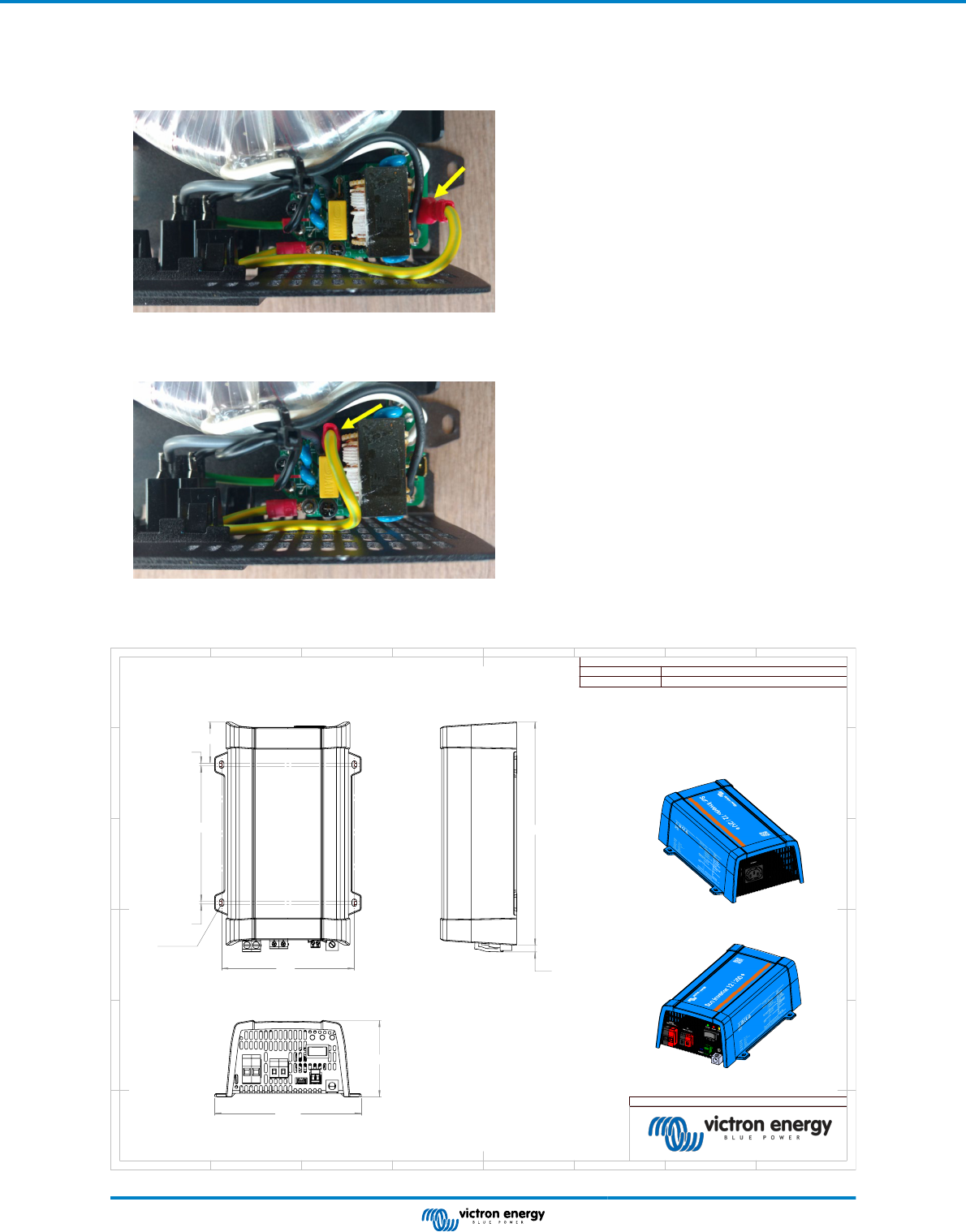
In the pictures below the two possible connections of the PE wire are shown:
1. Neutral floating
Position of the PE wire (indicated by the arrow):
2. Neutral connected to protective earth
Position of the PE wire (indicated by the arrow):
7.4. Dimensions
146
45.4
3
149
3
R2.6(4x)
246
7.3
161.3
85
Rev01
Dimensions in mm
Dimension Drawing - Sun Inverter
SIN121251100
Sun Inverter 12/250-15 IEC
SIN241251100
Sun Inverter 24/250-10 IEC
D
E
F
C
1
2
3
4
B
A
3
2
1
5
C
D
4
6
7
8
A
B
8
7
6
5
F
E
SUN Inverter Manual
Page 29 Appendix
